


![]()
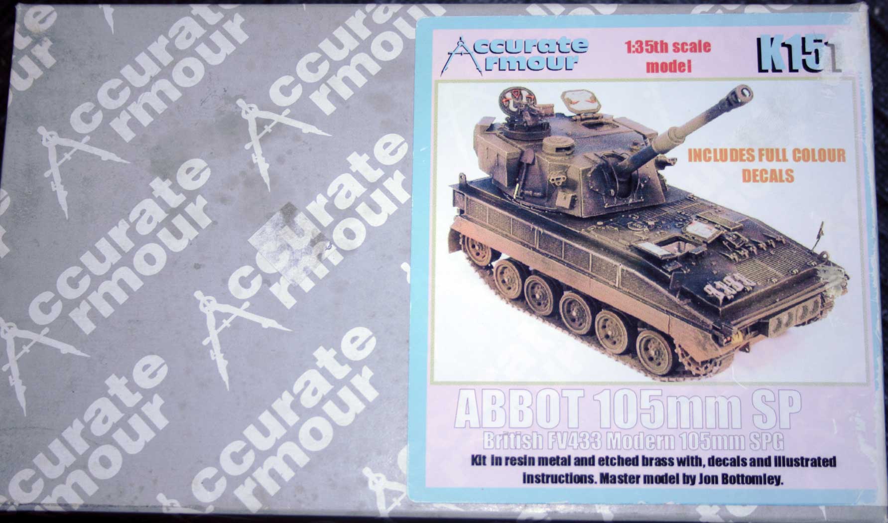
Abbot build. Click on pictures to view.
![]()
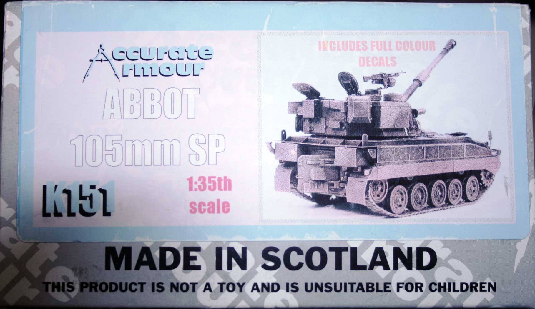
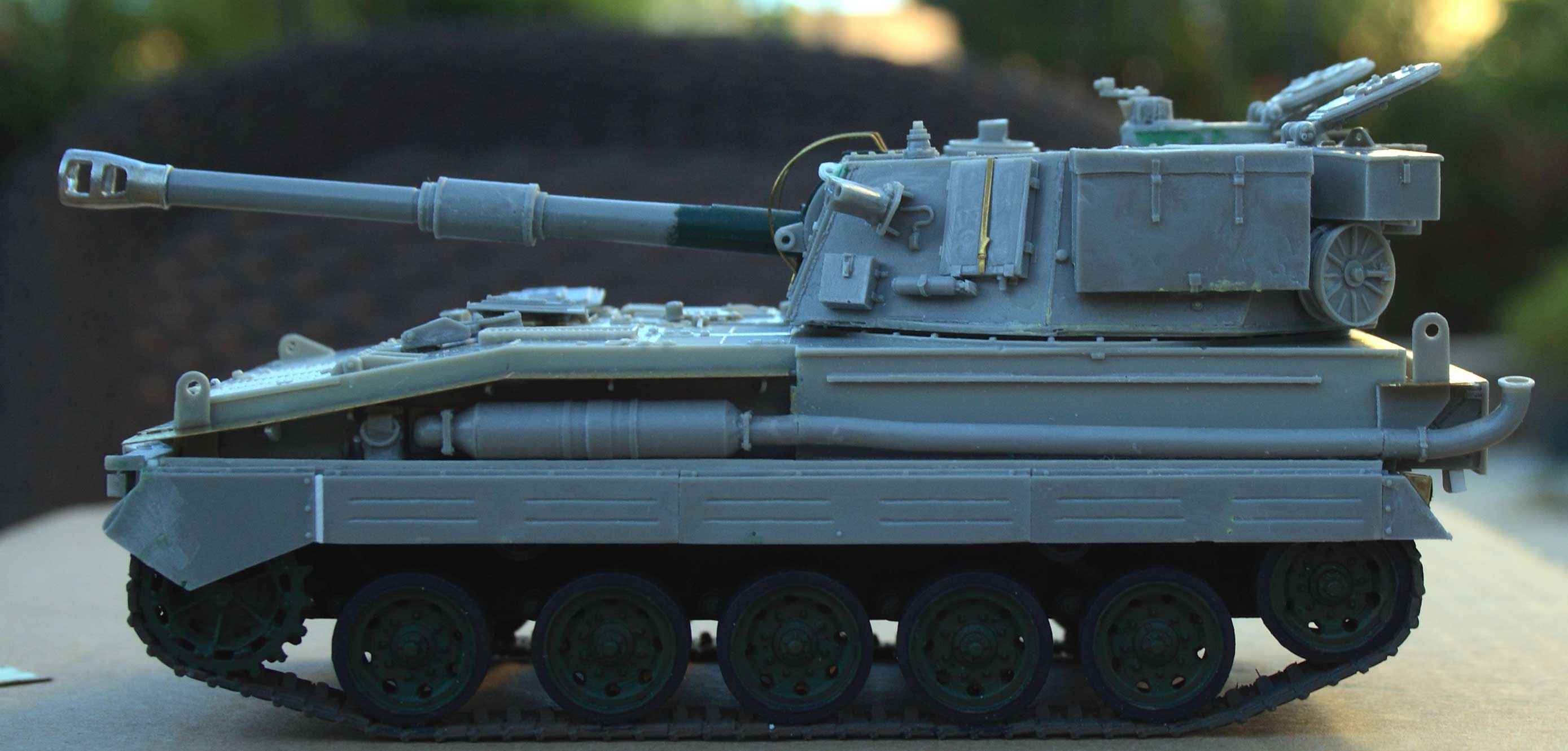
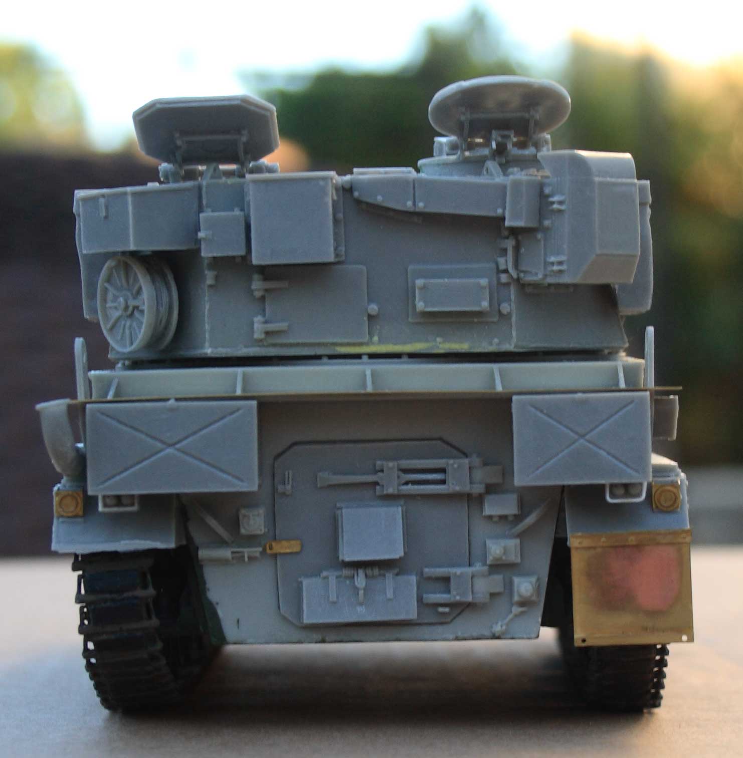
| Accurate Armour FV433 Abbot 105mm Self Propelled Gun (SPG). Note that kit is resin, metal and photo-etch and includes decals. | |||||||
|
| ||||||
| Box top | Box side | ||||||
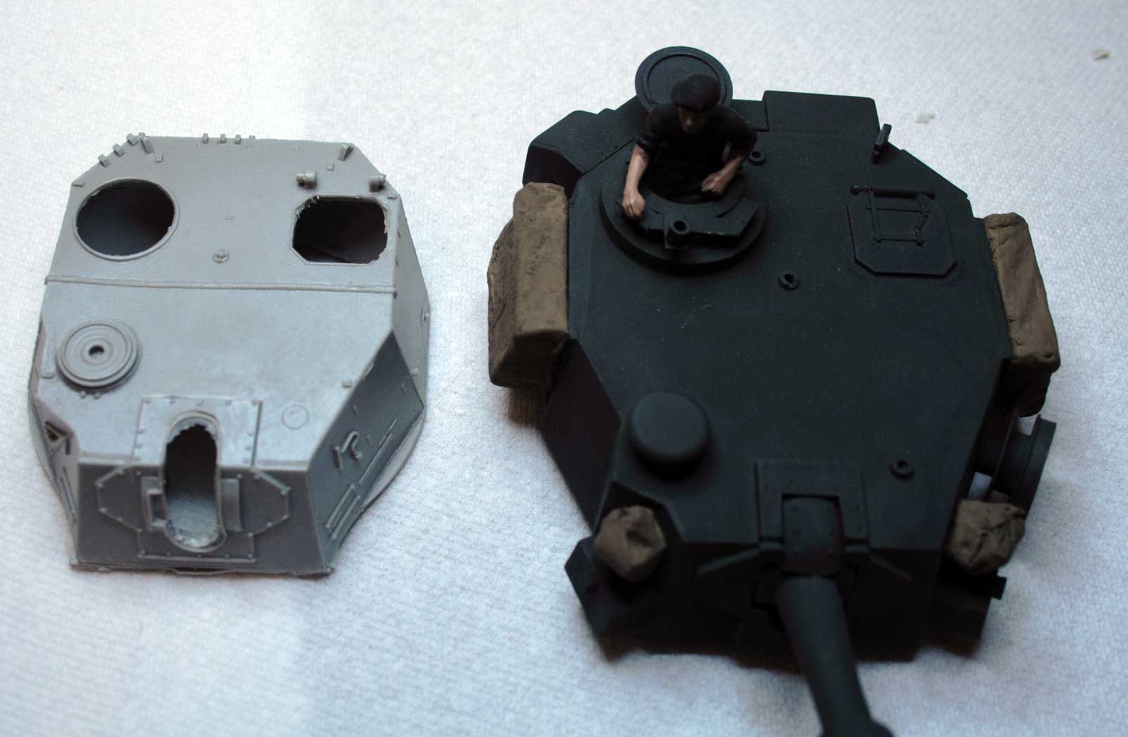
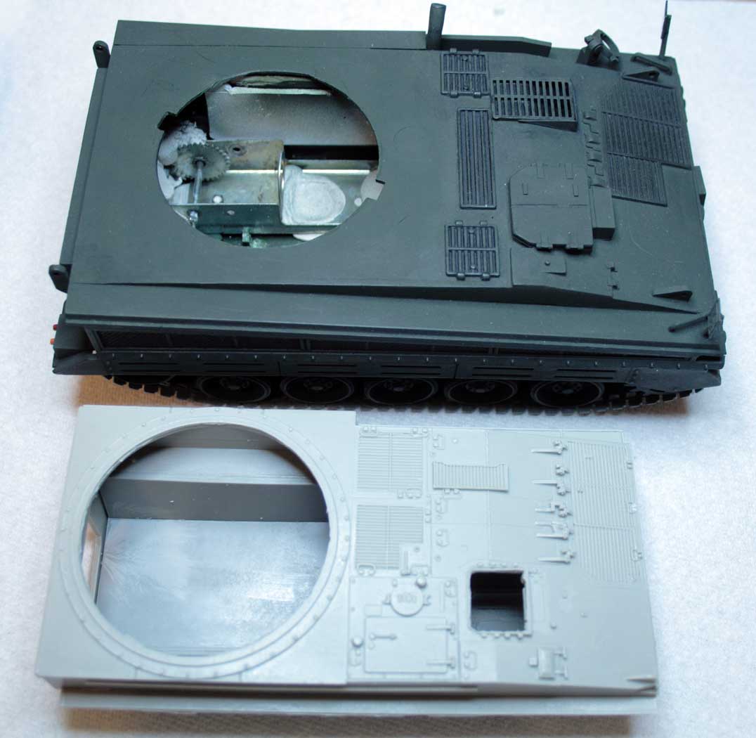
| I also compared some parts against the old and very approximate Nichimo kit and found out the old kit is a giant! Also it is a model of a prototype. | |||||||
|

|
|
|
| |||
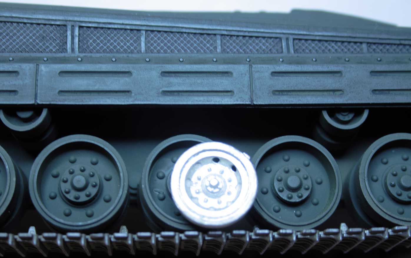
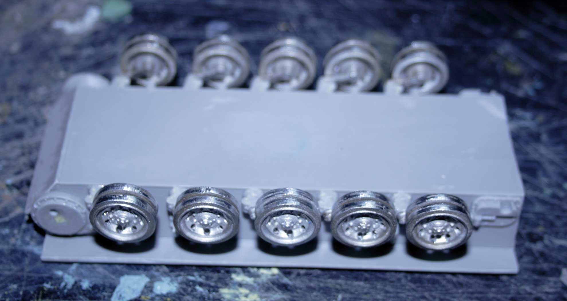
| AA turret vs Nichimo | AA turret much smaller! | Hulls compared. | Wow that Nichimo is huge! | Roadwheels. AA kit in raw metal. | |||
| 'raw' (i.e. no cleanup) Parts | |||||||
|
|
|
|
|
|
||
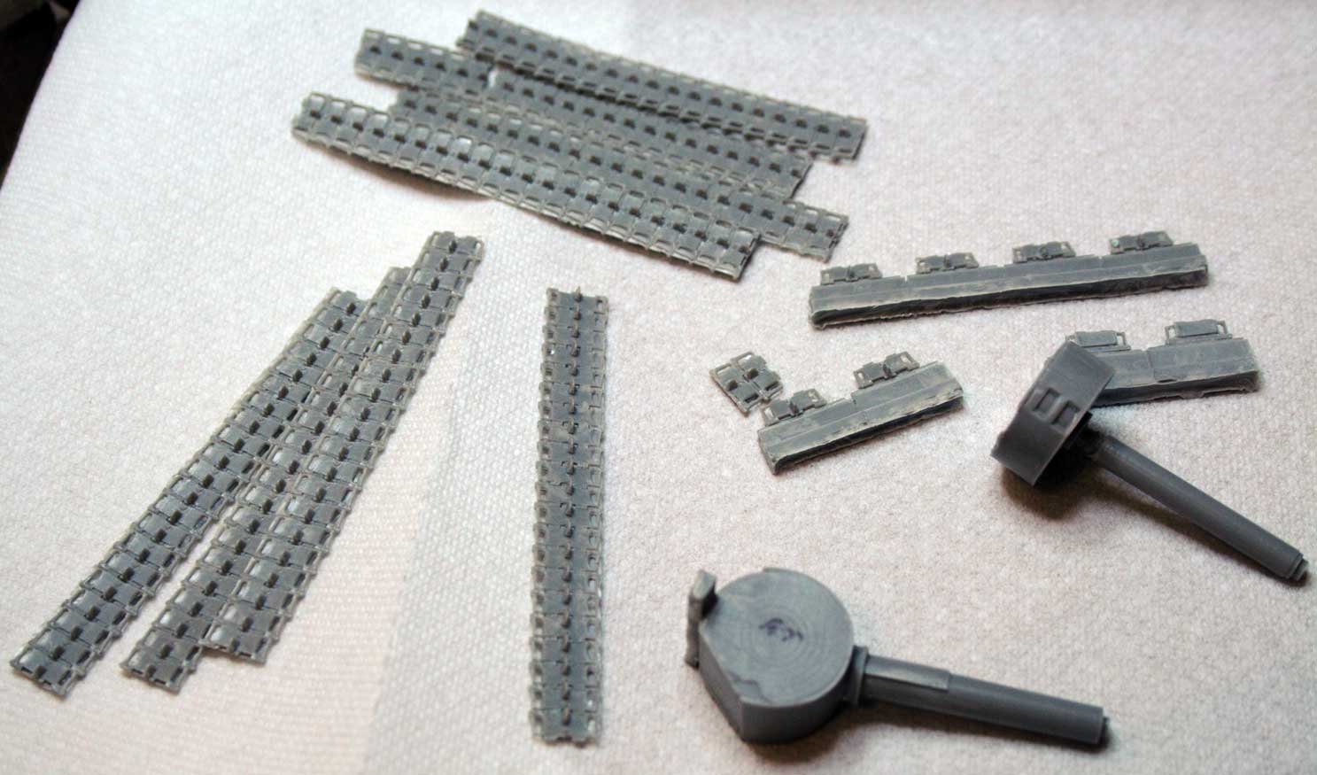
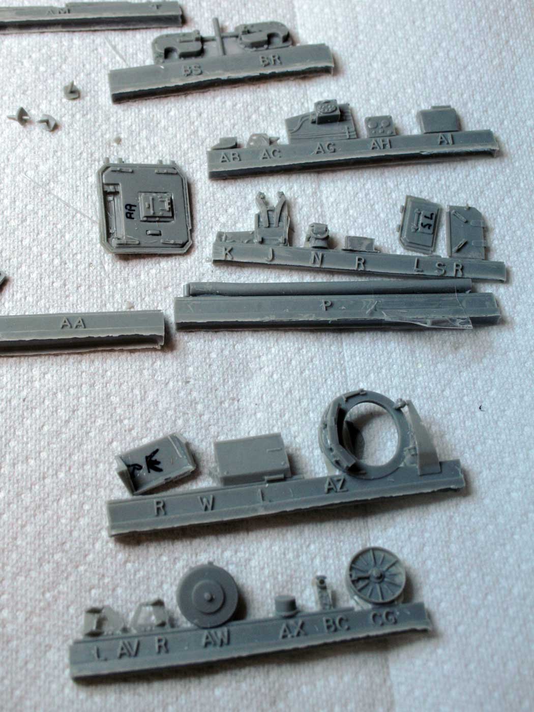
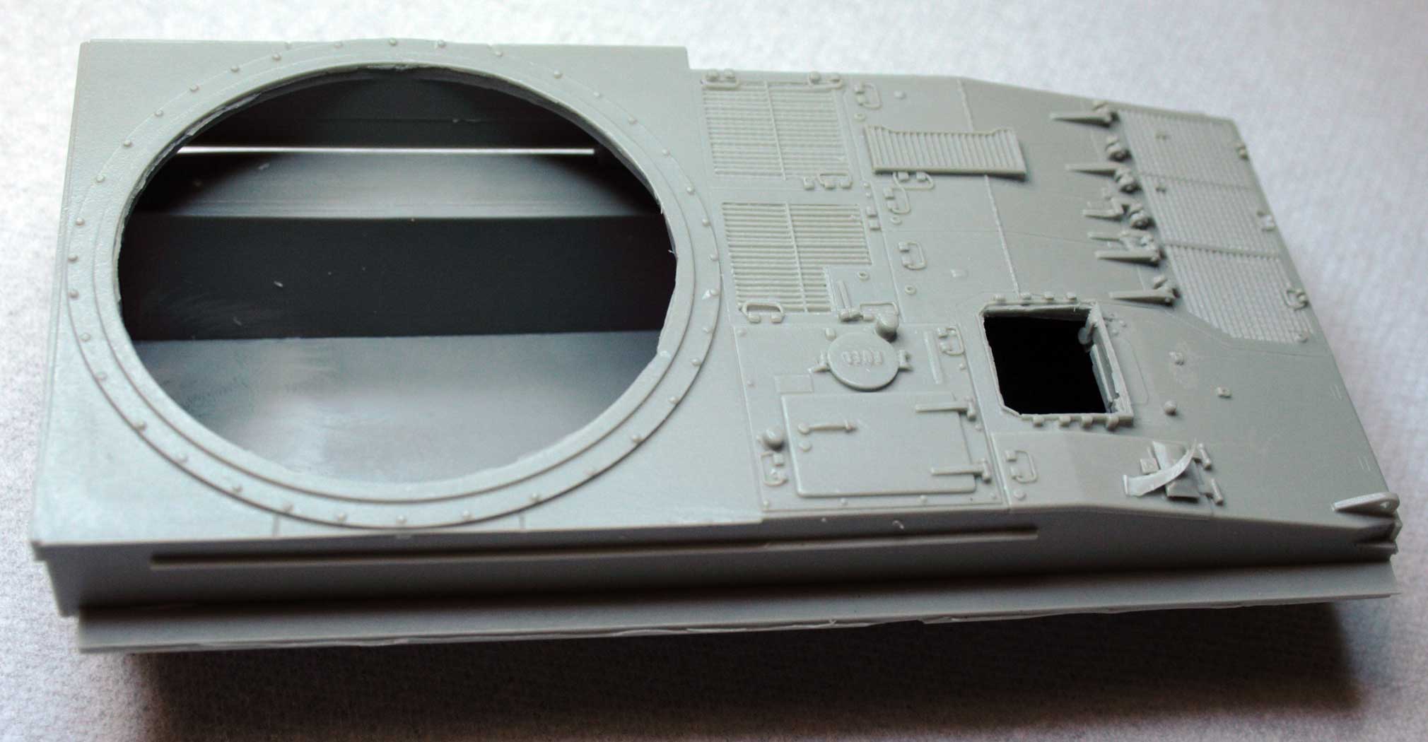
| Track and gun. | Suspension, exhaust etc. | Side panels and MGs | Turret ring, lights and hatches. | Turret accessories and rear hatch. | Hull top. | ||
|
|
|

|
|
|
||
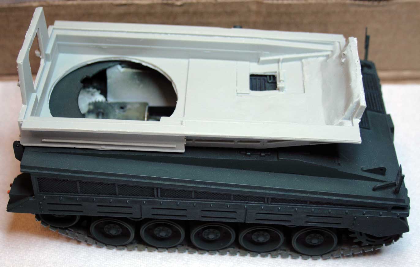
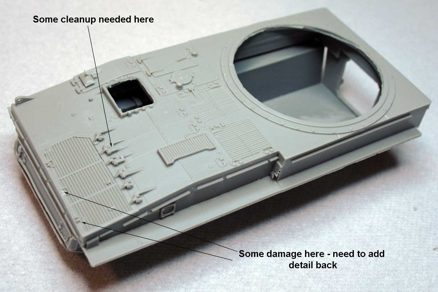
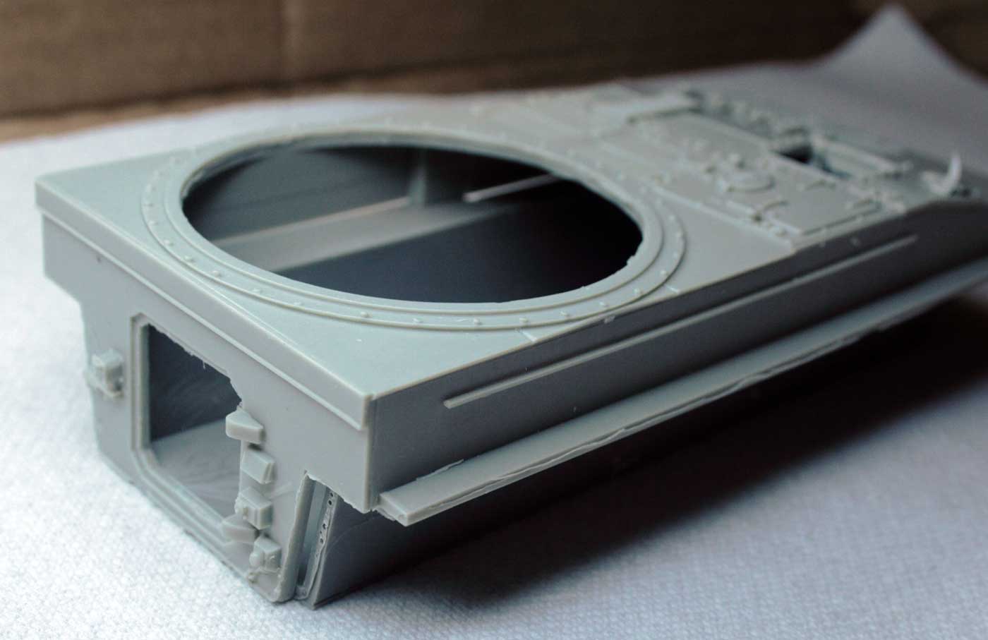
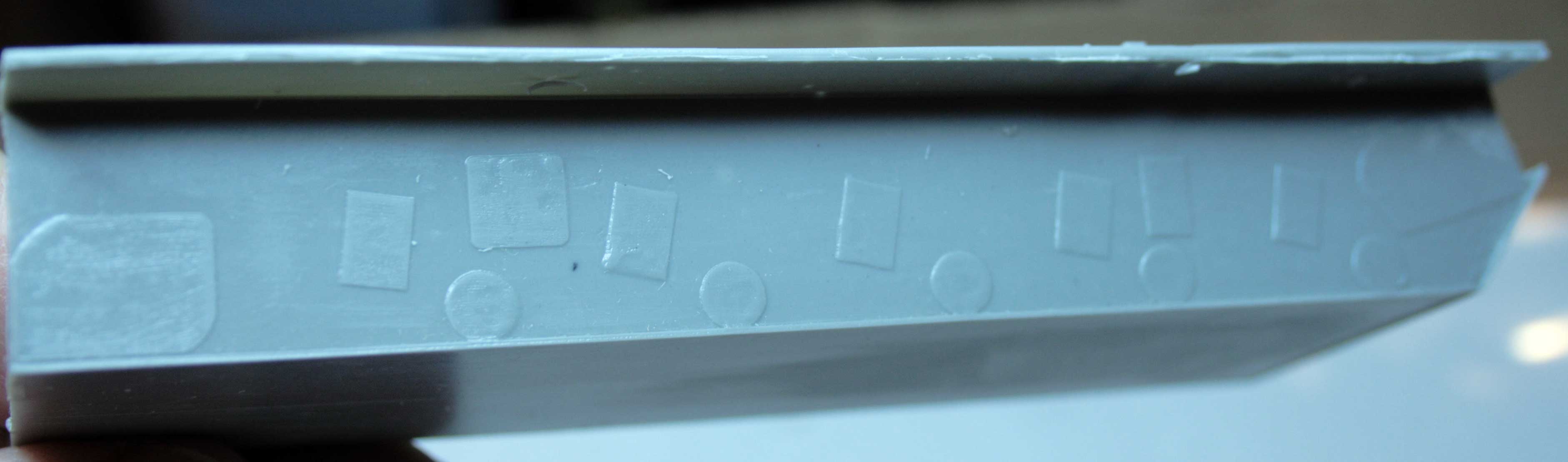
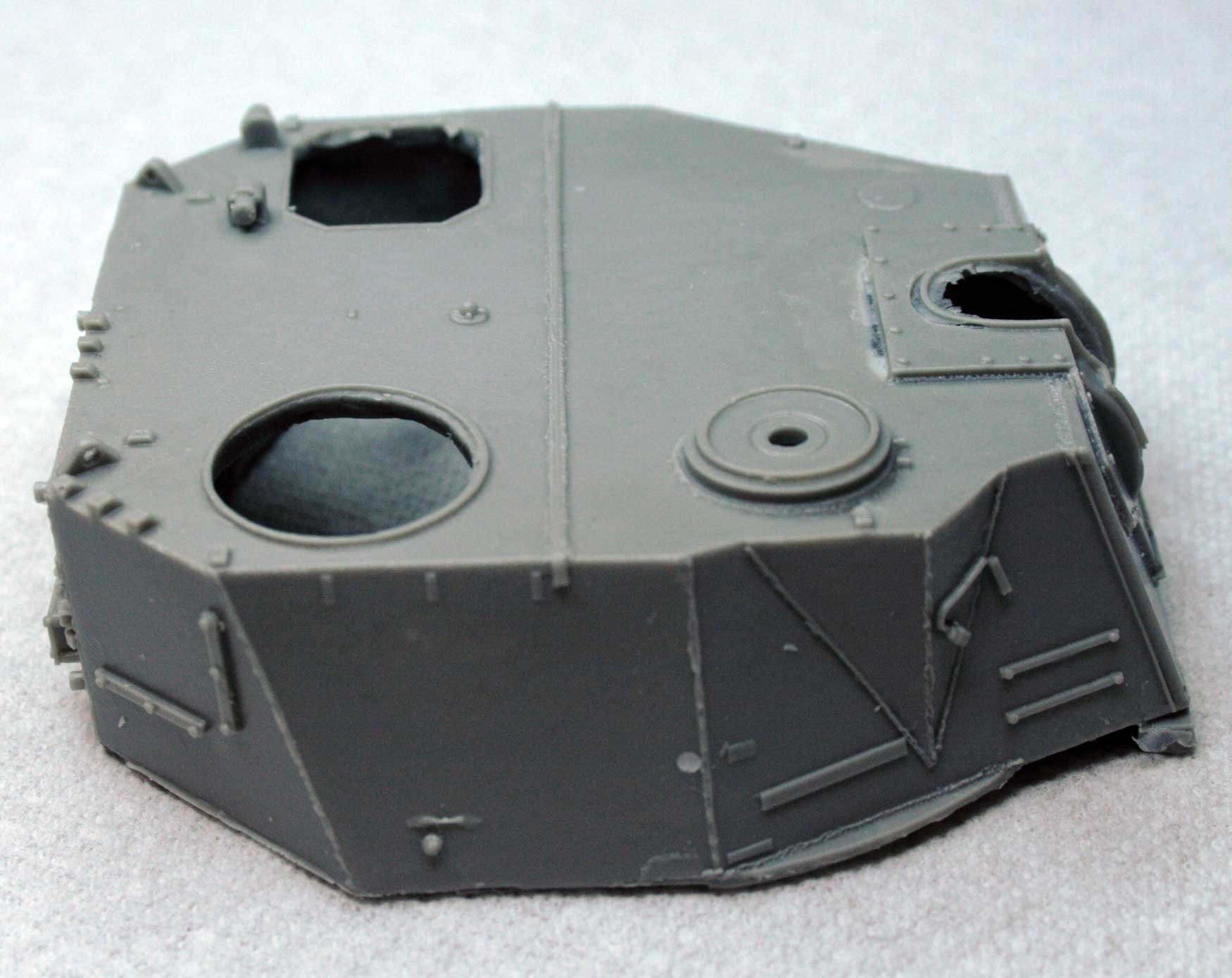
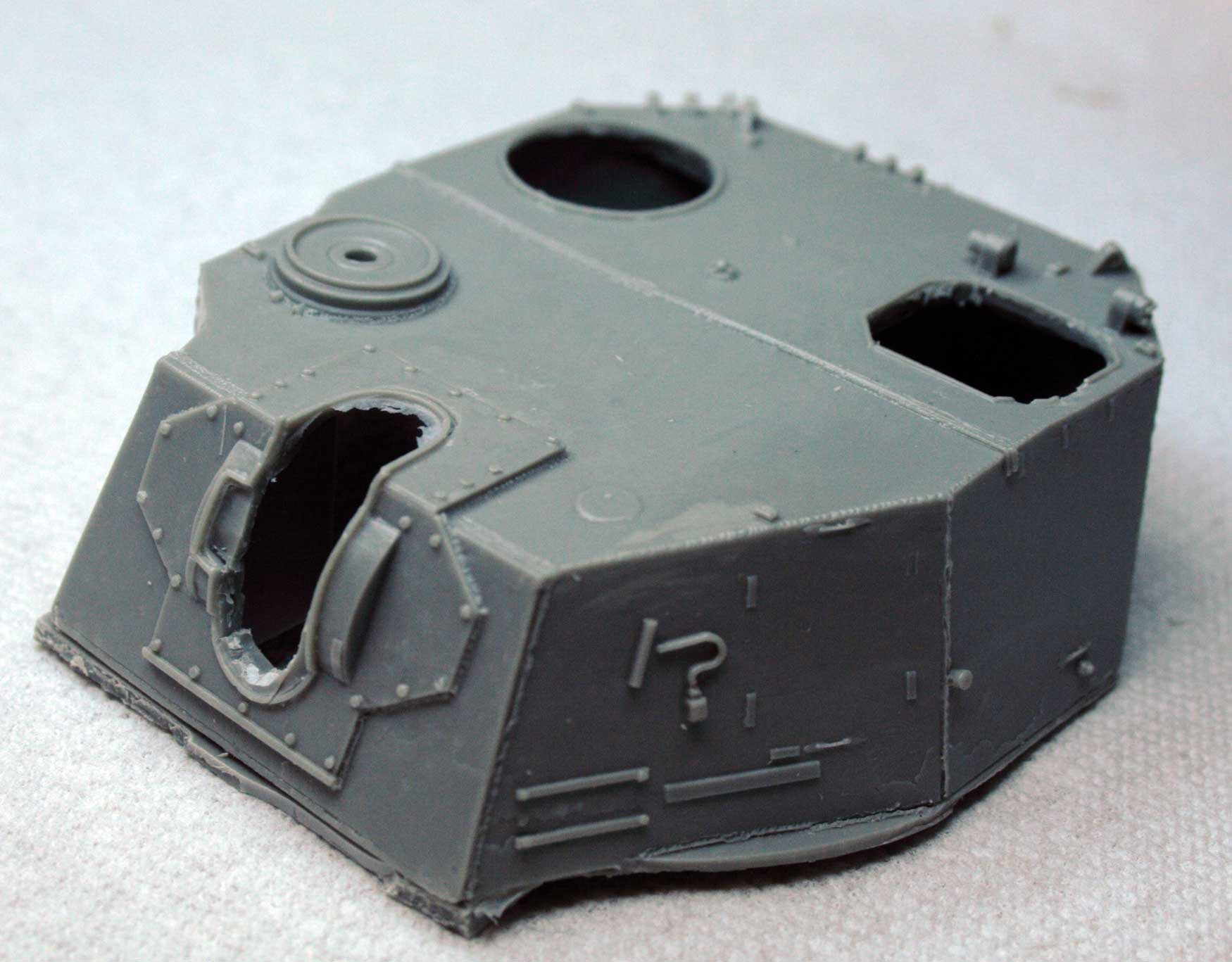
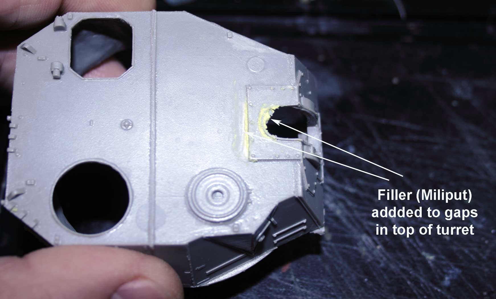
| Upper and lower hull. | Upper hull again. | Lower hull. | Hull bottom. | Hull side. | The turret has some gaps around the gun mount. | ||
|
|
|
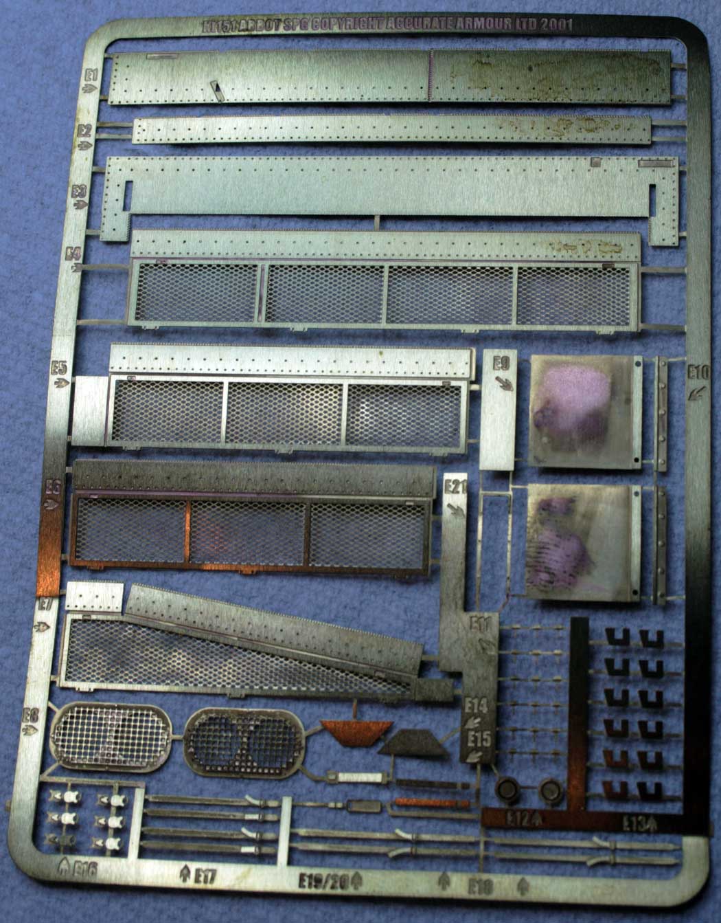
|
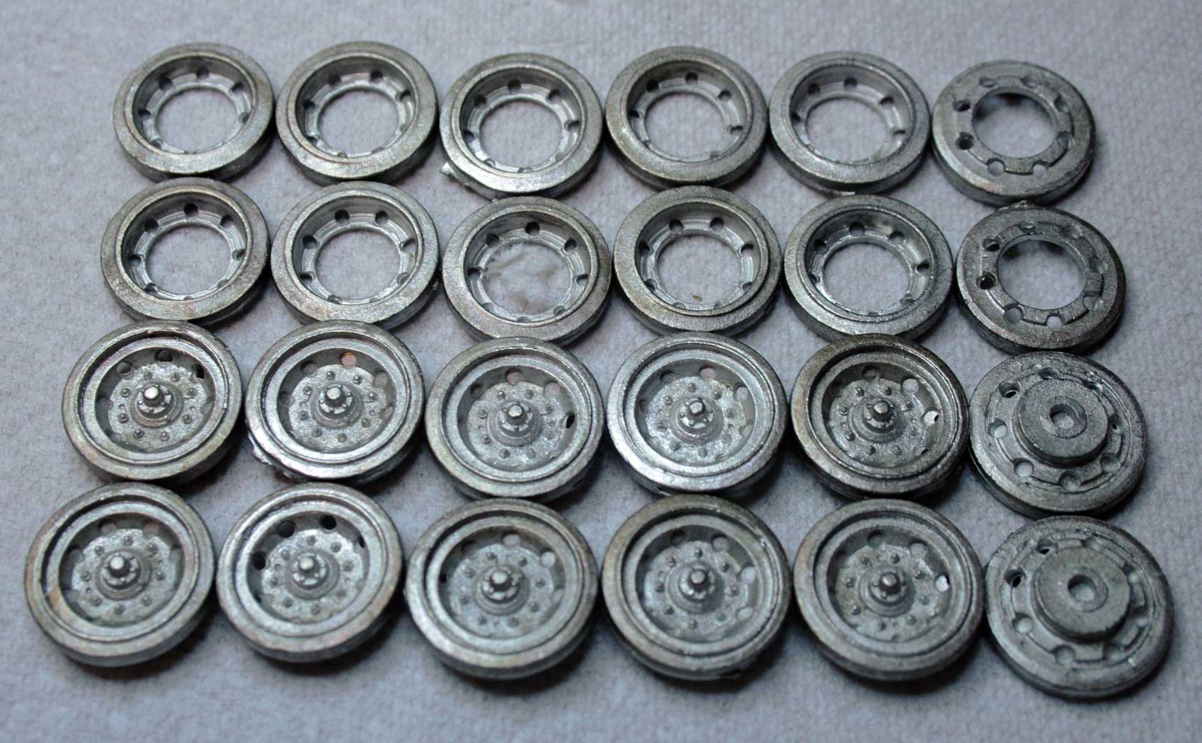
|

|
||
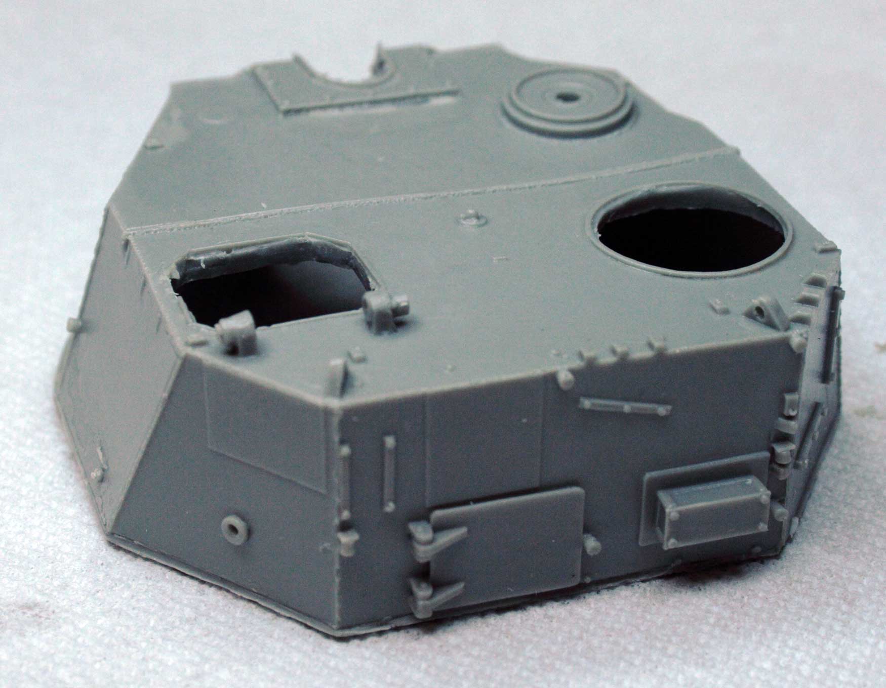
| Some rough edges to clean up. | Welding lines look good! | Decals. | PE | Roadwheels. | Suspension parts. | ||
|
|
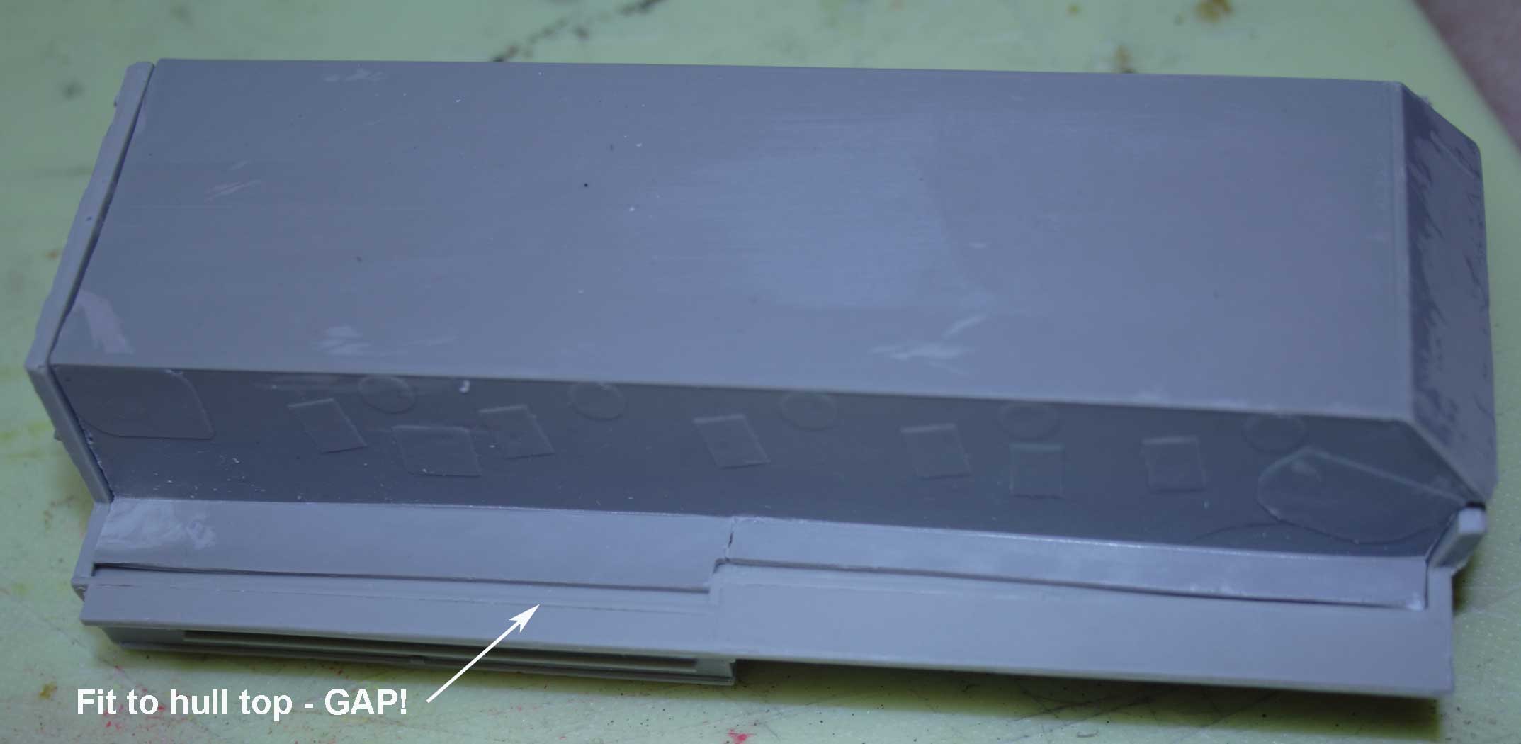
|
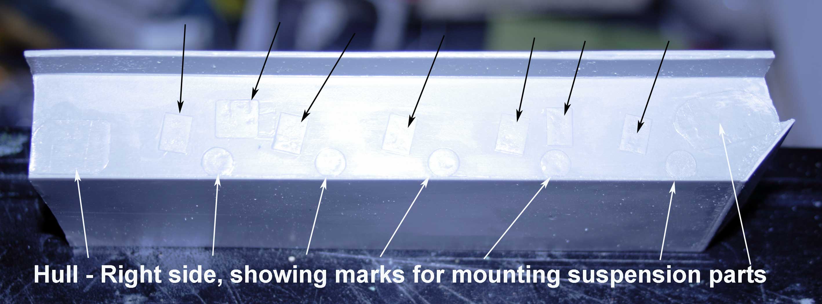
|
|
||||
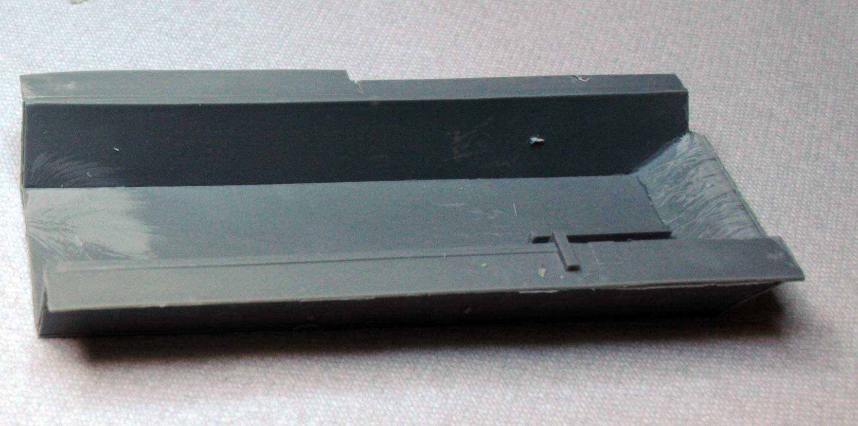
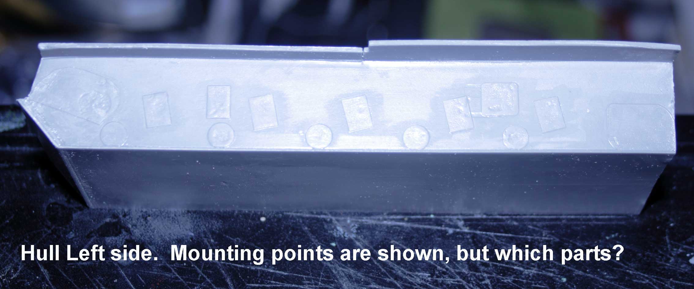
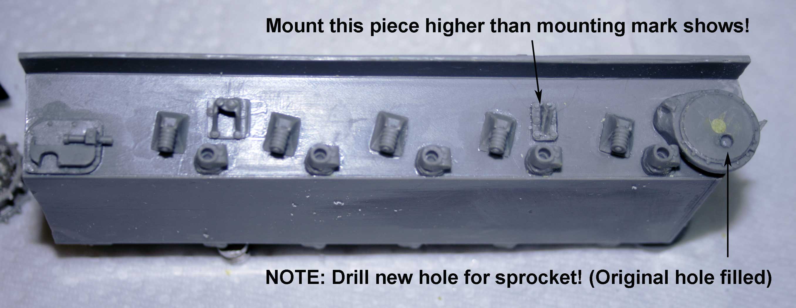
| Lower hull is warped. | See the gap when mated to the hull top? | Hull right side showing suspension mount points. | Hull left side. | ||||
|
|
|
|
||||
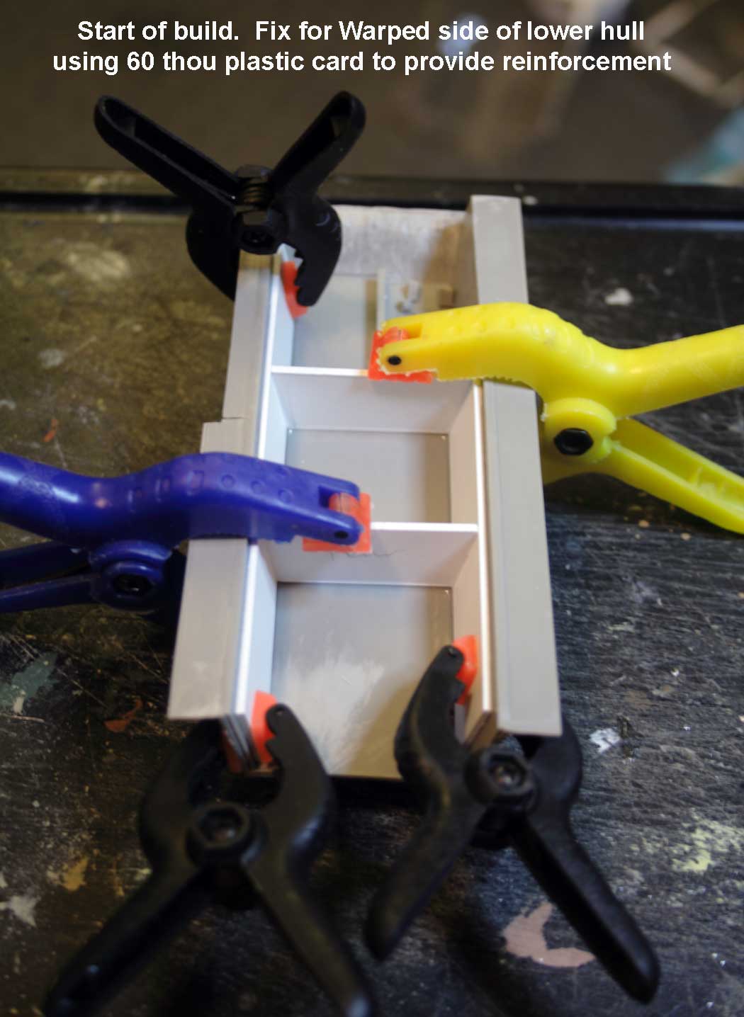
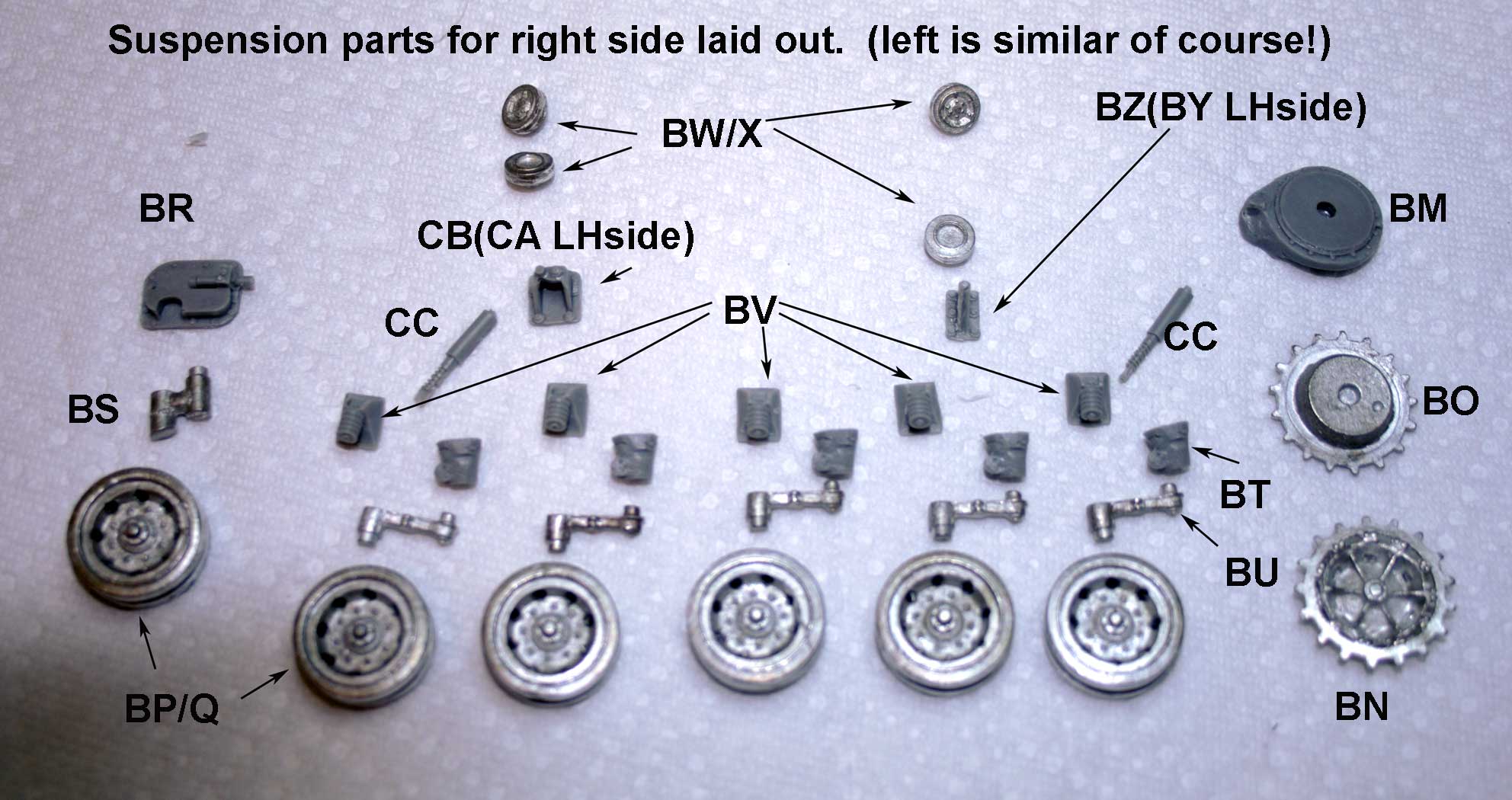
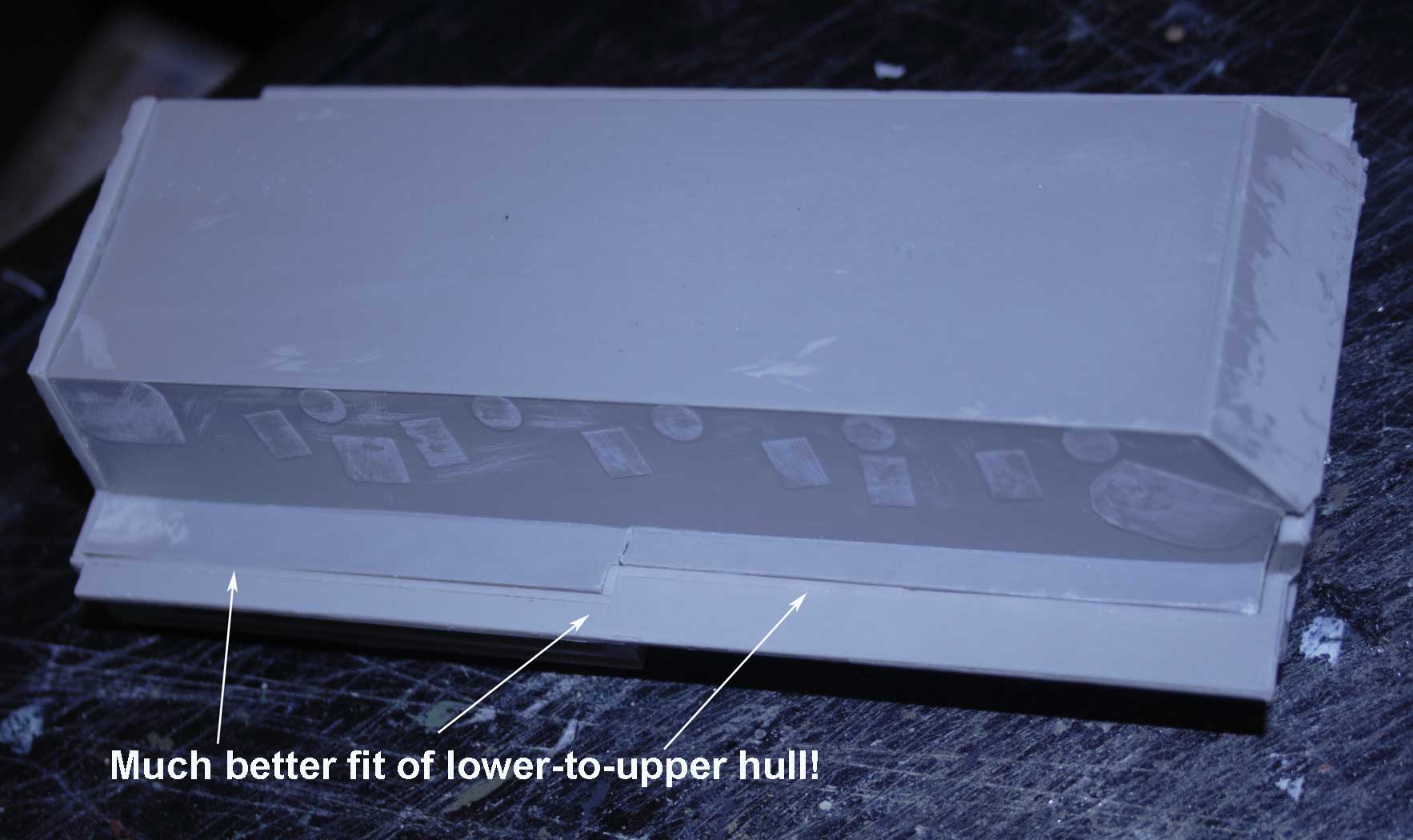
| Fixing the warped hull bottom with 60 thou card. | Suspension parts laid out and part numbers identified. | Revised fit of lower-to-upper hull. | Filler applied to turret. | ||||
|
|
|
|
||||
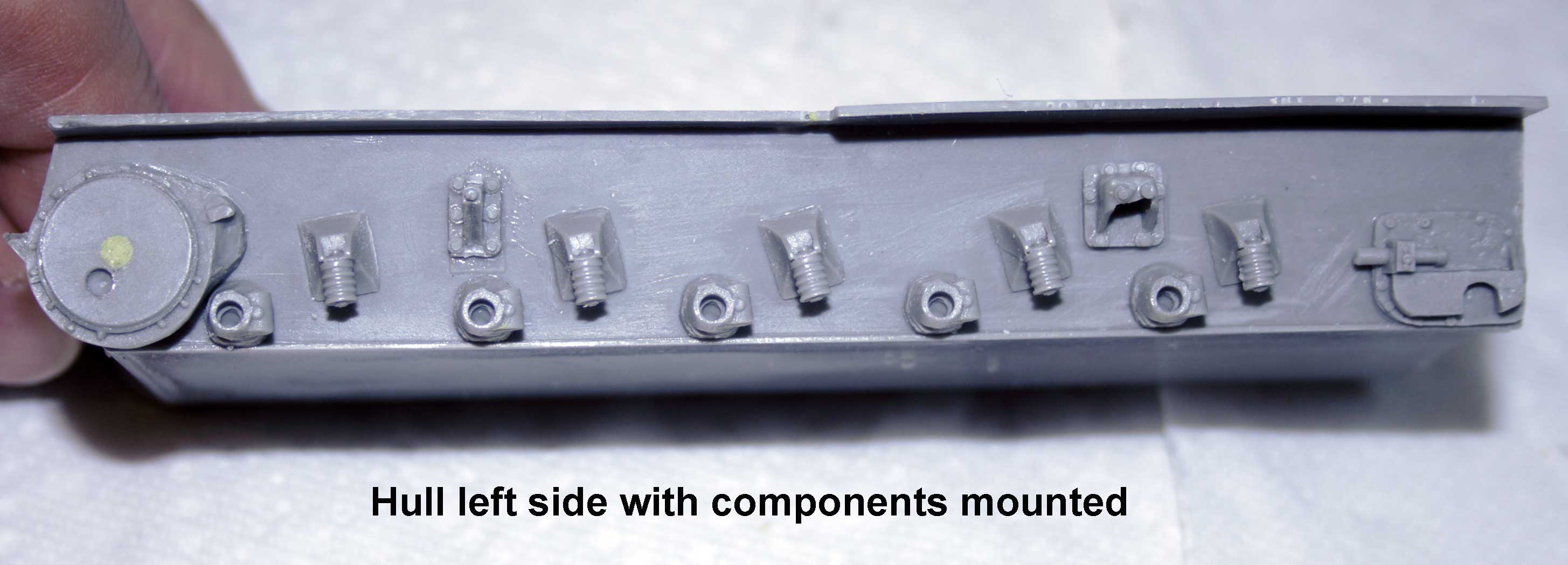
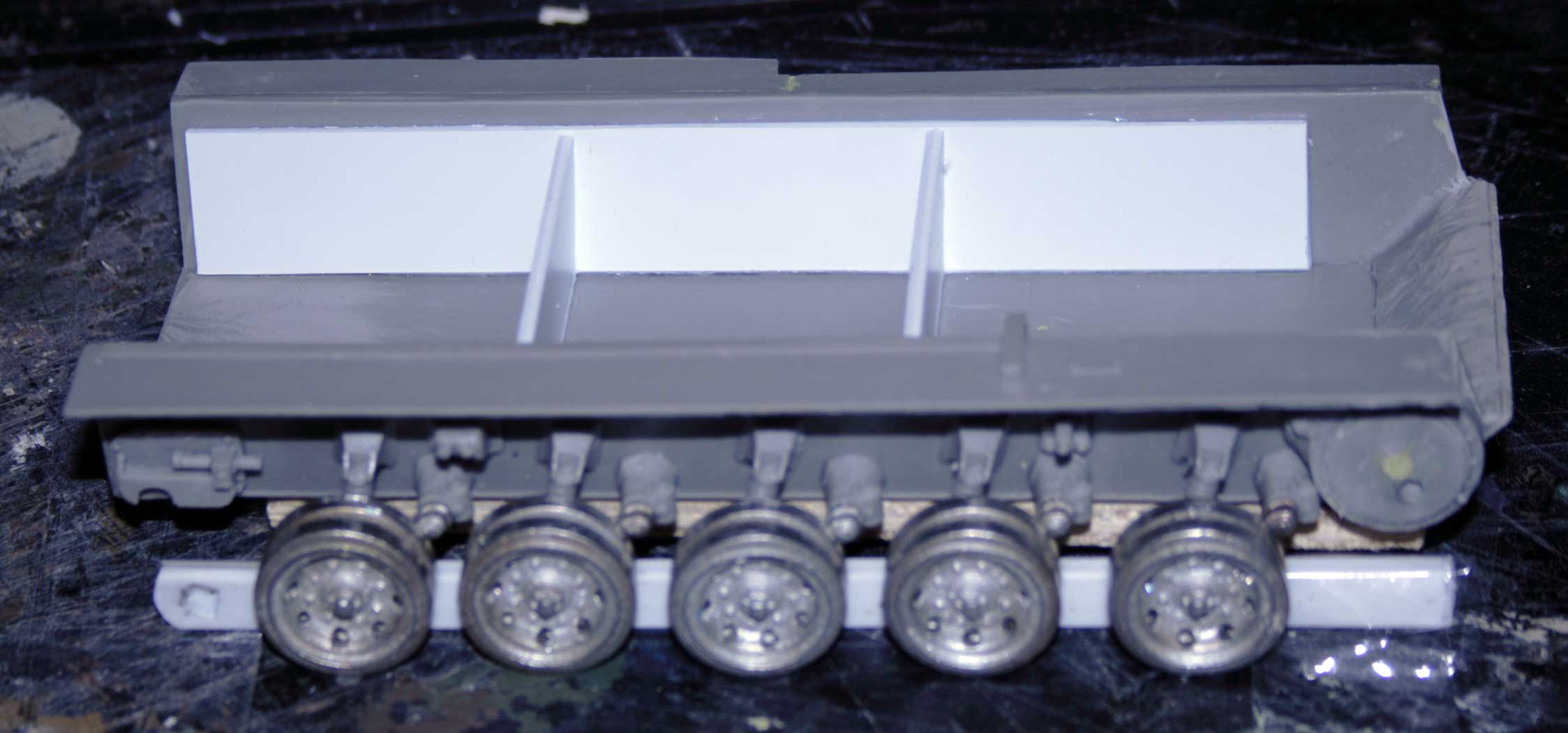
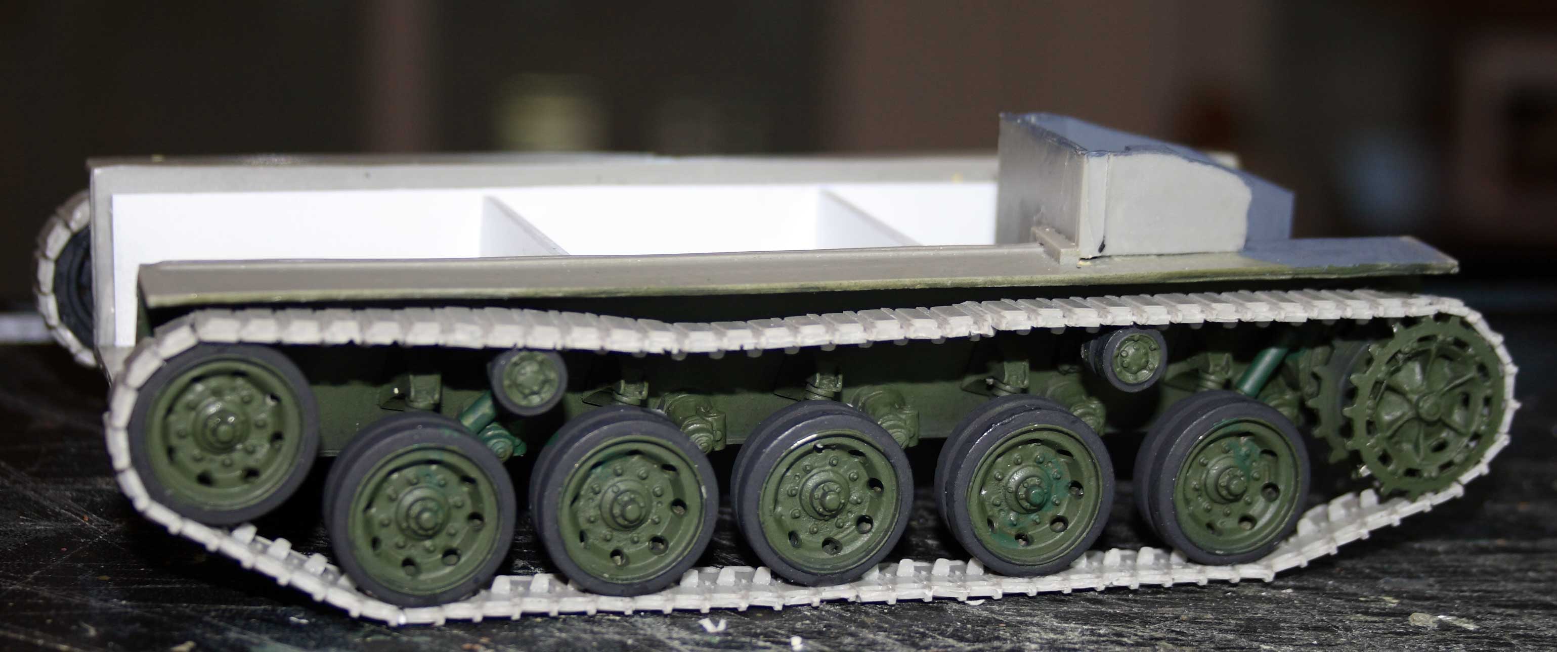
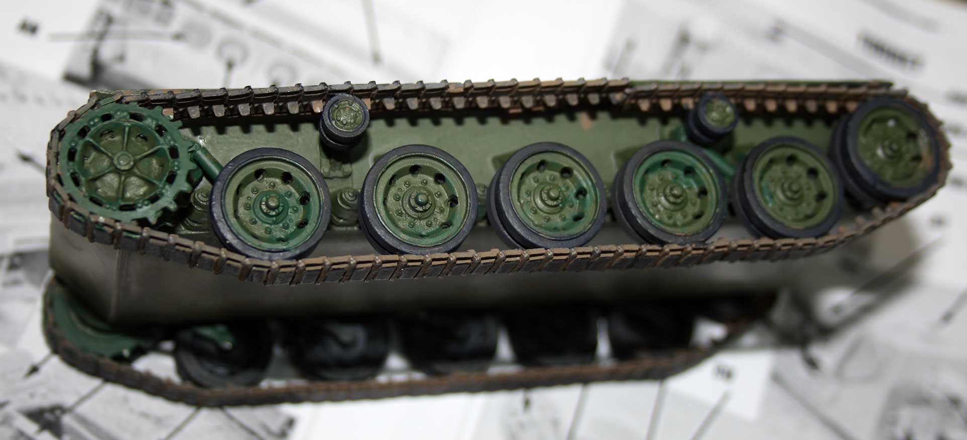
| Suspension parts applied right side. | Hull left side with parts mounted. | Attaching the roadwheels. | Roadwheels attached! | ||||
|
|
|
|
|
|
|||
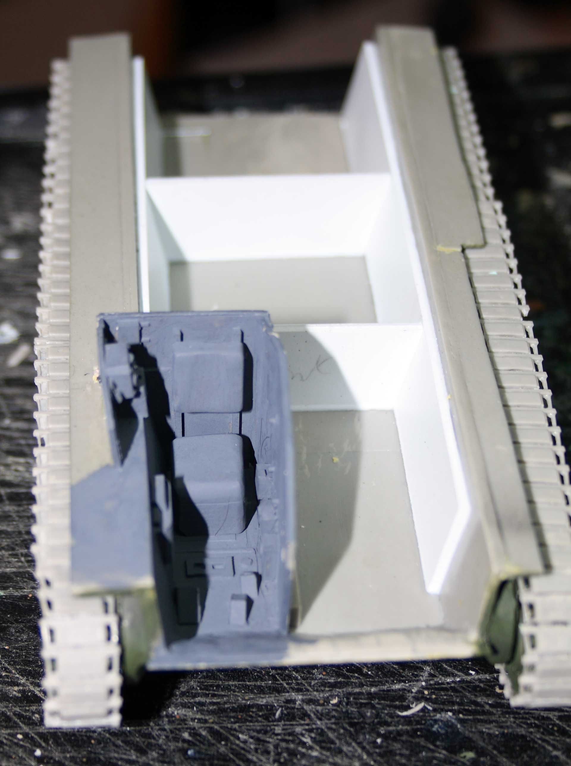
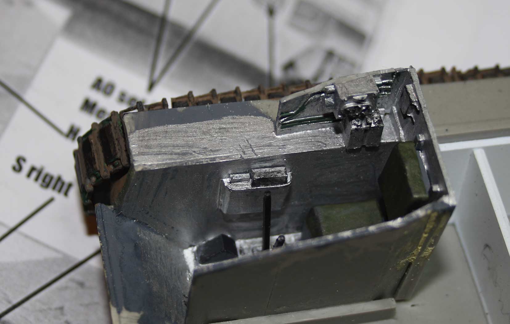
| Sections of track and track straightening jig. Note the damaged section bottom left. | Tracks assembled. Best pieces used on bottom - not-so-good pieces on top. | I didn't dare use a hairdryer - I cut individual links for sprocket and idler. Note the damaged track - maybe some mud will be required? | Driver's compartment being painted prior to installing hull top. | Finished driver's compartment. This will only be seen through the hatch. No driver figure so this detail can be seen! | |||

|
|

|
|
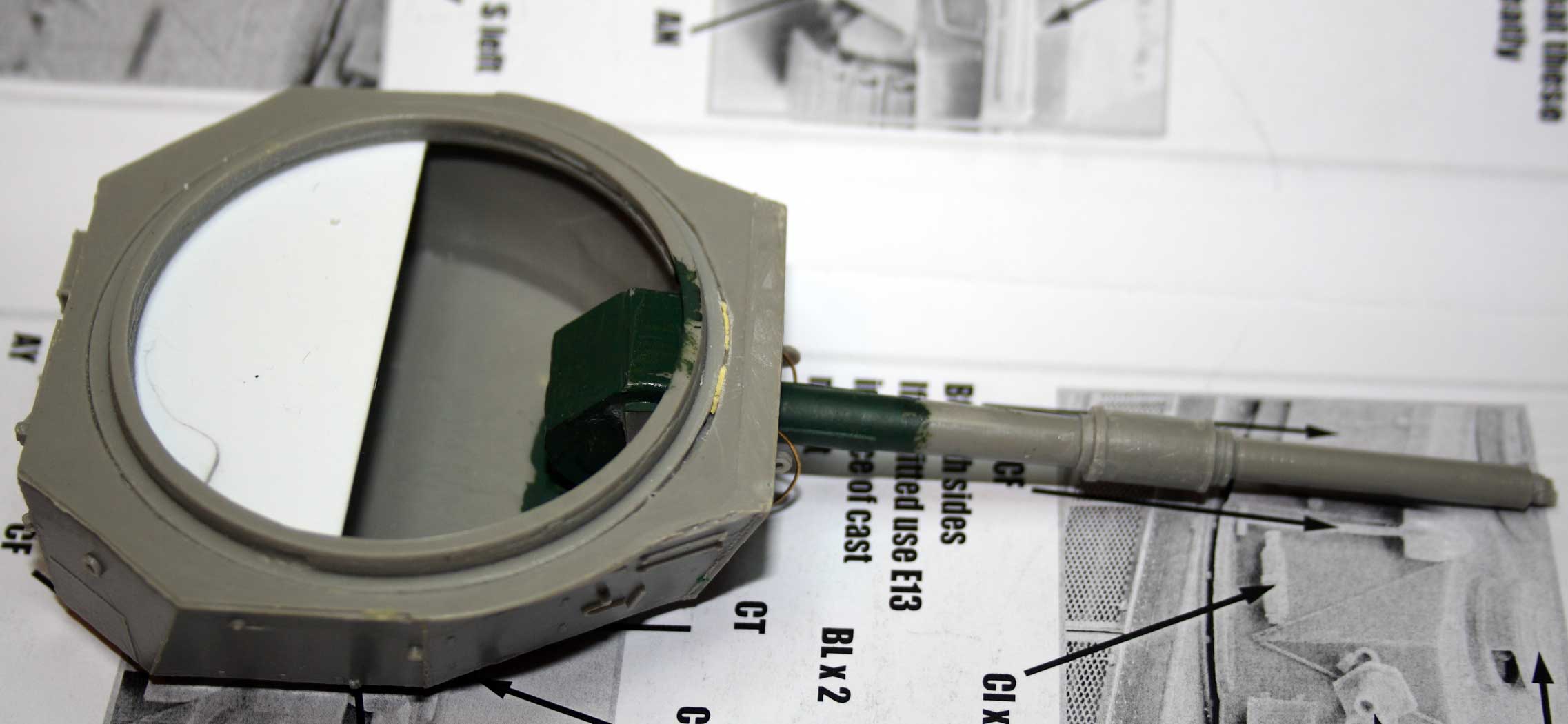
||||
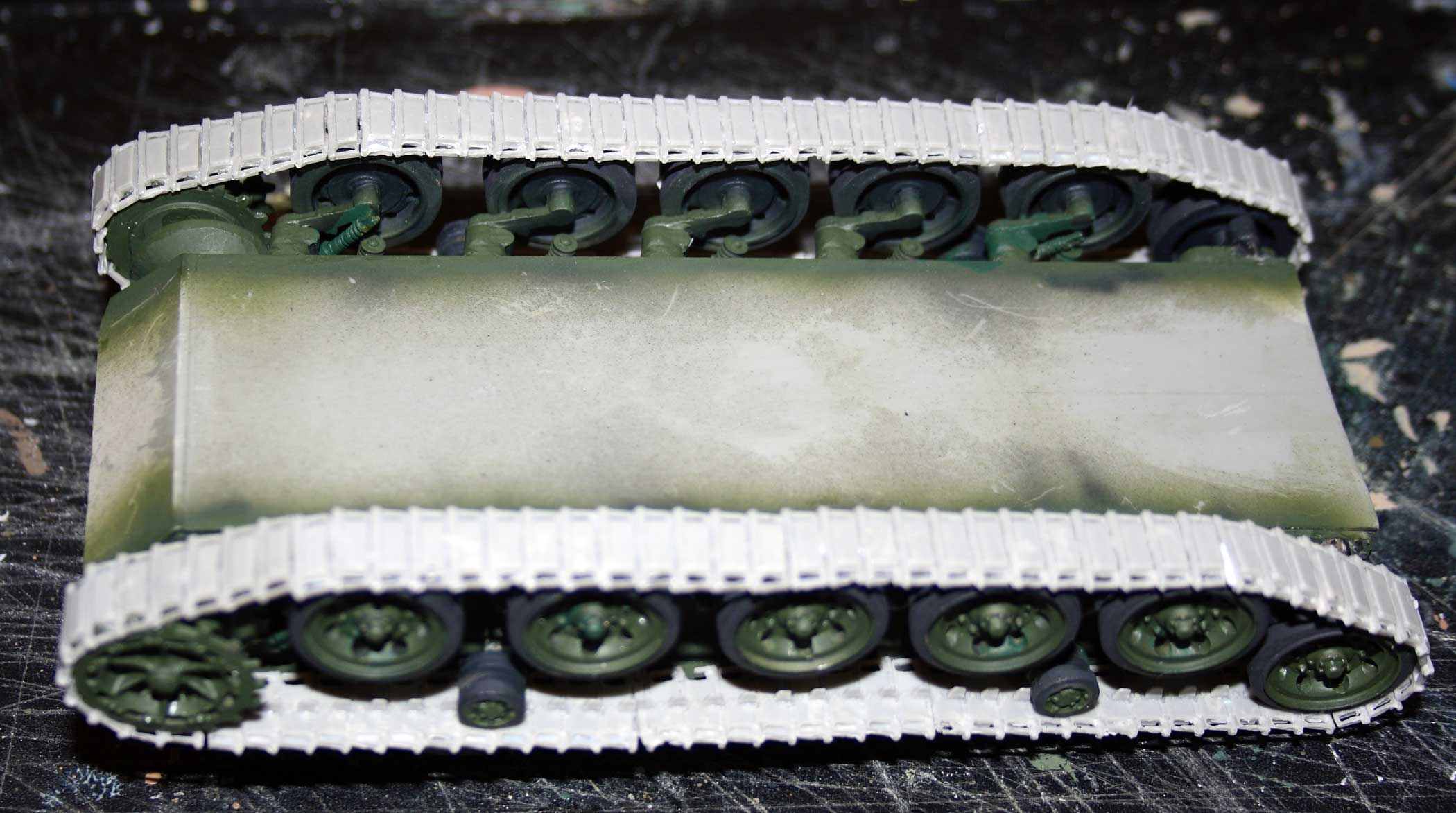
| Painted inside of driver's hatch area with instrument panel. All looks pretty rough from this angle! | Painted tracks (not final) but prior to hull top install. | Progress on turret and gun. After flirting with a movable gun I opted to glue it in position. | Under side of turret showing the ring glued in and platform for figures (white). | ||||
|

|

|
|
|
|||
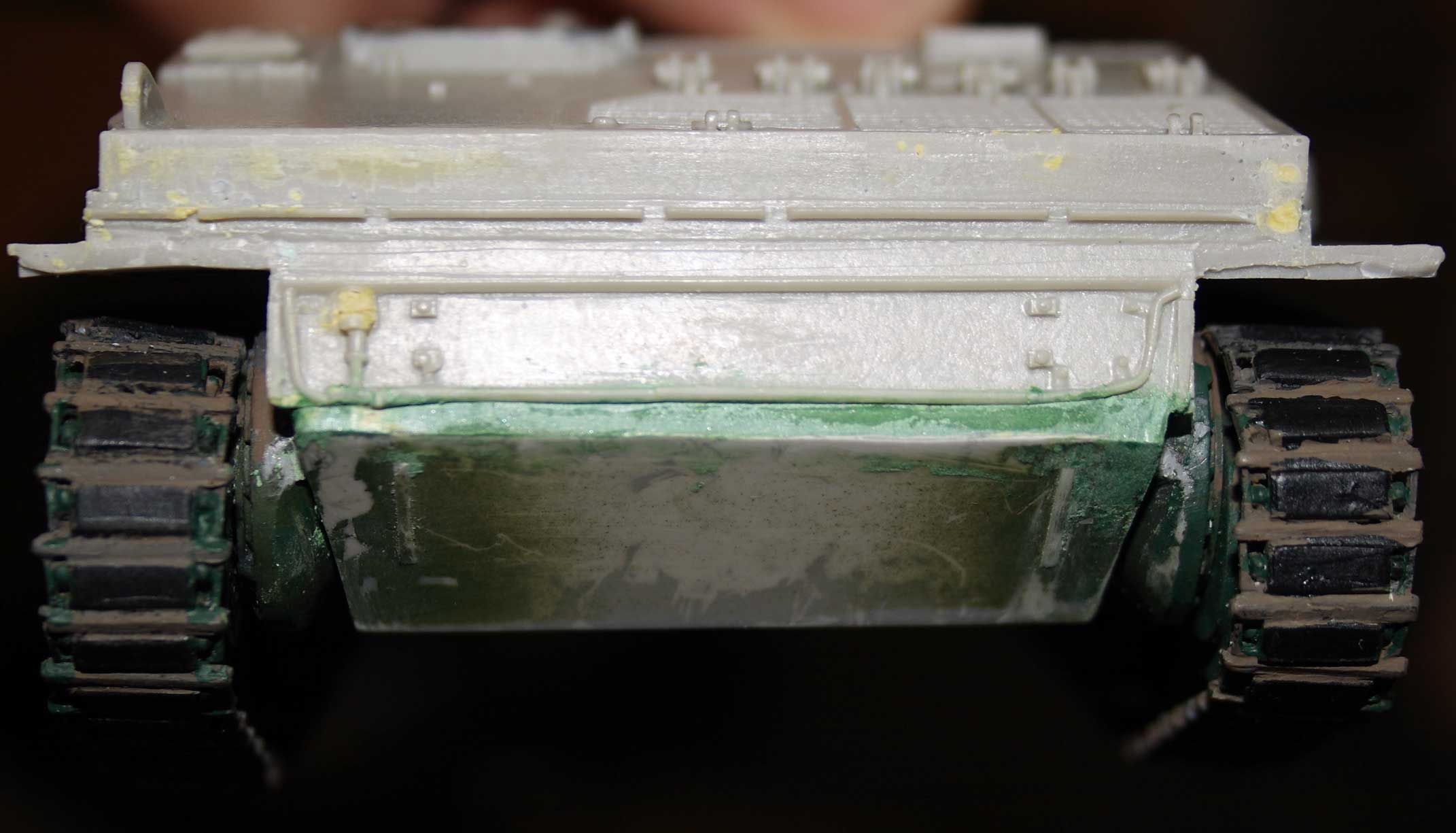
| Hull top installed - but oh dear - front is not even, lined up or true! | Complete enough for paint. The sides need painting before adding the PE mesh. The flotation screen goes on top of the PE. | I tried to tidy up the front with some plastic card. Also note where I had to repair the track after I damaged it. | Exhaust pipe on left side of vehicle. Note plastic card filler on side skirts. Some putty cleanup need on turret bag. | Yes I knocked off a mudflap while trying to photograph, and yes, nothing perfectly lined up. | |||